
What you will get out of this
If you build on nRF parts, this is what is in here.
- Building against the nRF Edge AI add-on when it is not in the stock manifest. What a plain Toolchain Manager install does when it meets
CONFIG_NRF_AXON, which is abort on four undefined Kconfig symbols, and the west workspace that fixes it. - A keyword model trained in Nordic's Edge AI Lab, running inside a Zephyr application. How the generated C drops in, what actually executes on Axon and what stays on the Cortex-M33, and what the model costs in flash and in RAM.
- A camera that runs its own detector, hung off an nRF part with no MIPI and no application processor. SPI at 8 MHz, an I²C bridge at
0x0c, and why a frame never has to reach the MCU at all. - One shared buffer, sized from measurement rather than from arithmetic, with the compile-time assert that stops it drifting, and a zero-copy borrow that avoids a second buffer on a part with 512 KiB of RAM.
- Keeping a hard real-time audio thread fed while the camera streams. Thread priorities, the DMIC slab that kills the audio path if it starves, FPU sharing, and the system workqueue that Axon's completion path shares with your own work items.
- Getting throughput out of BLE on a peripheral that ships JPEGs. The ATT MTU that fills exactly one radio packet, the 2M PHY request that has to be made twice, and the trailer that keeps bounding boxes attached to the frame they were inferred on.
- What the development kit's VDD:IO rail does at power-up, why it stops a camera module from booting, and the single GPIO that works around it.
- Every number with the conditions it was measured under, including the ones that are not yet good enough to claim more than they do.
Most of it is the ordinary work of fitting something ambitious inside a part that was not built for it: where the constraints were, and which trick got past each one.
Where this started
This began at the Embedded Vision Summit in Santa Clara, last year. We already had YOLO running on a Sony IMX500, inside a two-stage pipeline of our own: the first stage classifies the object we are looking for, on the device, and the second stage, in the cloud, identifies the individual one. The split is the whole point. Identifying an individual is not something a small NPU is going to do with YOLO, and without the first stage there is no way to avoid shipping every image to the cloud just to find out whether it was worth shipping. A Raspberry Pi did everything the sensor did not, and the Pi was the problem. It never sleeps. A product that has to live on a battery cannot carry a processor that idles in watts.
That is what I talked about with Jackson Lee, Arducam's founder, at that Summit. He knew the other half of it already. Arducam have been putting cameras on microcontroller platforms for years, so the limits of a small MCU are the first wall they hit too, and we had been building on Nordic parts for just as long. Between us the diagnosis took no time. An nRF part has no high-speed MIPI input, and if it had one it would have nowhere to put the result: an uncompressed 608 × 608 RGB frame is 1.11 MB, against 512 KiB of RAM on the entire device.
Two companies with the same interest and complementary halves of the problem, cameras on their side and Nordic on ours. What came out of it was the shape of the thing that would have to exist: a module that removes the need for MIPI, running the network on the sensor's own die and handing back a verdict instead of pixels.
Arducam built that module. Their technical thread with us opened in April, and at this year's Summit Lee said the thing that started the firmware in this article: we are coming up with this module, why don't you test it.
We did, with what we already knew about YOLO and what we already knew about Nordic parts. On 15 June the camera answered on an nRF54LM20 DK. Everything below is what it took to get from there to a unit that runs all day.
What the part is actually doing
Worth stating plainly, because it is the reason this was worth writing down.
The nRF54LM20B is doing three jobs at once here, and none of them crowds out the others. Axon runs the keyword-spotting model, 289 KiB of weights in flash and about 32 KiB of RAM, continuously, on every 10 ms window of 16 kHz audio, with no wake word and nothing gating it. That model is running the entire time the camera is streaming, and it is what turns a spoken word into a filter over what the sensor sees. At the same time the part drives a camera that does its own inference, over nothing more exotic than 8 MHz SPI and 100 kbit/s I²C, and ships JPEG frames to a phone over Bluetooth LE using the SoftDevice Controller with a deliberately chosen 247-byte ATT MTU. All of that runs alongside a hard real-time audio thread that must never miss its 40 ms window, at 28% of flash and 66% of RAM. The single largest RAM consumer is not either neural network. It is the camera frame buffer.
The architecture came out of the two blockers above: no MIPI input, and nowhere to put a frame if there were one. Once the detector lives on the sensor die, the MCU stops being an image processor and becomes what it is good at: a supervisor with a radio. And a supervisor with an NPU sitting idle is a waste of an NPU, so the design gave the product a voice.
Architecture: three threads, one shared buffer, and a strict order of precedence
The firmware is a C-only Zephyr application with no framework underneath it. Everything below runs on a single nRF54LM20B: the camera link, the audio pipeline, the radio, and all of the reassembly and decoding in between. The interesting part is not any one stage. It is what each one is allowed to interrupt.
Three threads share the machine. The microphone thread runs at K_PRIO_PREEMPT(0), strictly above everything else, because the PDM driver holds only four blocks, about 40 ms, of audio before it needs dmic_read() to drain one. If the camera loop ever starves it, the driver's buffer slab runs dry and the audio pipeline dies for good. The main thread owns the camera: it reads SPI, reassembles frames, parses tensors, and applies the filter. The BLE frame-send thread exists for exactly one reason: chunking a JPEG of roughly 70 KB over the air takes hundreds of milliseconds, and the main loop cannot stop draining the module's forwarder for that long without the module overflowing it and splicing the next frame into this one.
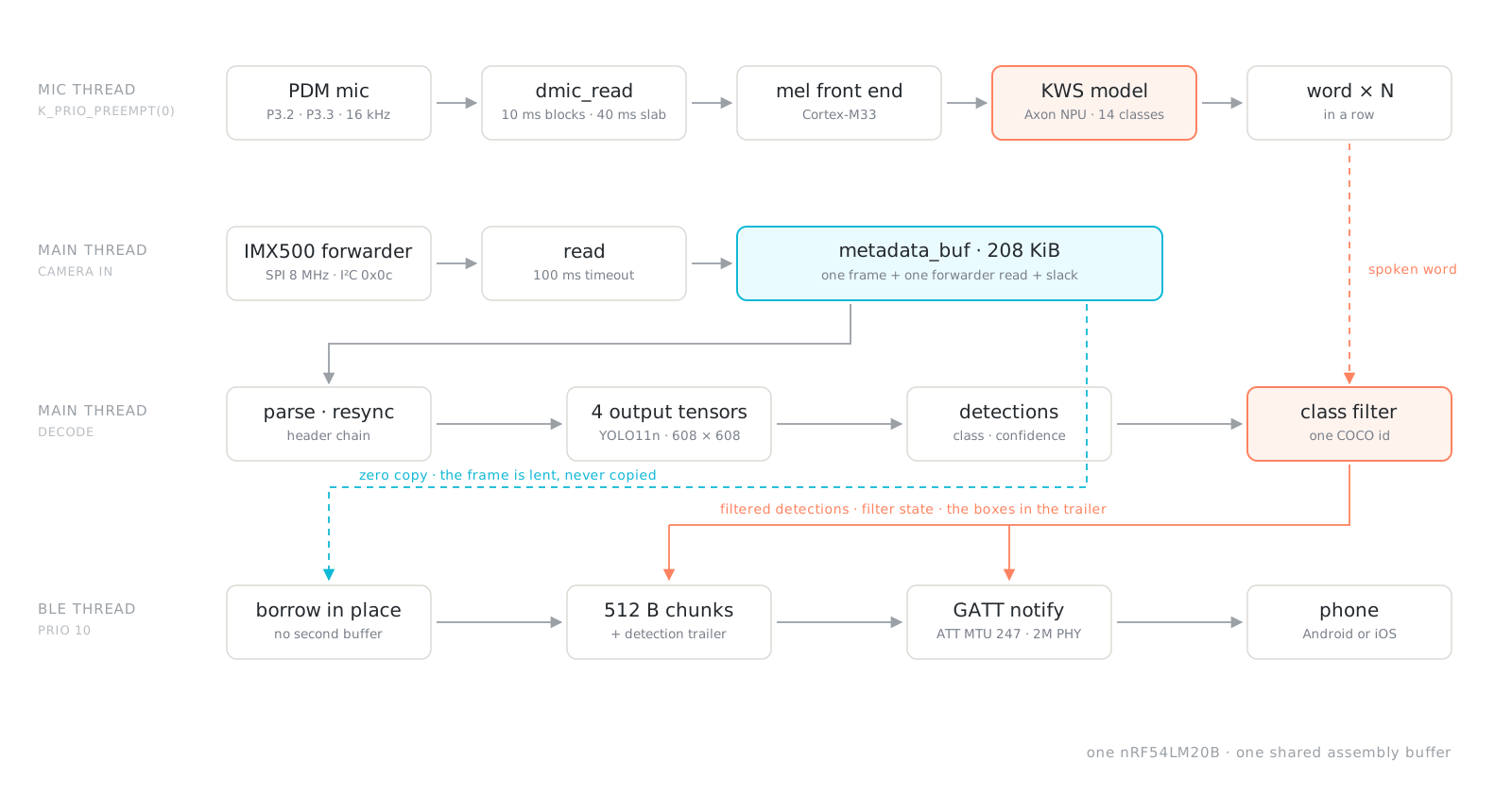
Figure 1. The whole firmware on one page. Coral is the voice path: the keyword model runs on the nRF54LM20B's Axon NPU, and the spotted word becomes the detection filter. Cyan is the single large allocation, which the BLE thread lends frames out of rather than copying.
01Reset and attach. An open-drain GPIO pulses the module's RUN pad, then the driver waits for the I²C bridge at 0x0c to answer: a 10 s readiness budget per probe, and a retry loop behind it that does not give up.
02Open the sensor and start the stream. Quick open, full open, or a bare attach, chosen from the module's own boot status. YOLO11n at 608 × 608 is already resident in sensor flash.
03Reassemble frames from partial SPI reads. The forwarder hands back whatever it has buffered so far, so frames are stitched together across reads in one shared buffer.
04Decode four output tensors. Boxes, scores, class ids, and a valid count, each with a per-model layout and quantisation the module does not declare.
05Spot a word and set the filter. The keyword maps to a COCO class and becomes the only class that survives to the phone.
06Notify: detections, filter state, frame. Three characteristics on one custom GATT service, with the boxes riding along in a trailer behind the JPEG.
Stage 1Getting the module to answer, and knowing which door to knock on
Opening the camera is not one operation. The module can be cold, warm, already streaming from a previous run, or not powered yet, and each of those states wants a different approach. Most of the bring-up code is there to recognise which one it is in before touching the bus.
A camera that is not there is not an error. The camera's 3.3 V supply is not always present when the DK starts. On the bench it is often connected once the board is already running. So the firmware treats a missing module as a normal state rather than a startup failure: it polls BOOT_STATUS and brings the pipeline up whenever the module reports ready.
The retry loop has to be careful about two things. First, noise: a module that is not wired up yet would otherwise produce one error per second forever, so the first three attempts log in full and after that it speaks up every tenth. Second, silence: a retry loop that says nothing is indistinguishable from a hang, which matters here because a module clamping SCL or SDA makes every TWIM transfer block for the full driver timeout. A single probe can spend seconds inside one read, so the loop clocks the bus free from inside the probe rather than only between attempts, and emits a heartbeat while it does.
A useful distinction on I²C. A 500 ms-ETIMEDOUTand a fast-EIOare not the same failure. The timeout means the module is on the bus and jamming it; the fast error means nothing is there at all. Telling them apart is the difference between clocking the bus free and waiting patiently for hardware that has not been plugged in.
Three ways in, chosen from boot status. Once the module answers, its boot status decides the path. A cold module gets the full open: reset, model load, configuration. A module that is already partway up can take the quick open, which skips work it has already done, though the quick open cannot load a model at any timeout, because the reset is a precondition for that, not an optimisation.
A module that reports itself already streaming gets neither. It gets attached to: issue nothing, just read. A reset or a stream-off sent to a warm module takes it back to a state only a power cycle recovers, so the right move is to leave it alone and start reading, which produces frames in about 2.3 seconds.
At boot status 2, the correct command is no command at all.
Stage 2One buffer, sized by argument rather than by guess
The module streams each frame into its forwarder progressively, and a single SPI read returns only what has been buffered so far. So frames do not arrive, they are reassembled. Reads append to one buffer, and complete frames are consumed from the front while assembly continues behind them.
That makes the size of this buffer the most consequential number in the firmware, and it is worth showing how it was derived, because the intuitive derivation and the measured one disagree.
The JPEG does not scale with the image. The intuitive sizing is bytes-per-pixel times pixels. Measured on device, a 320 × 320 preview and a 608 × 608 preview come back about the same size, 4.32 and 1.19 bits per pixel respectively. The module's encoder is rate-controlled to a fixed byte budget and lets per-pixel quality fall as the input grows, so the buffer is sized flat rather than per-pixel, and the firmware logs the preview's real dimensions and bits per pixel once per run to keep that checkable.
The same is true of the forwarder itself: a single read caps out around 71 KB no matter how large the frame being streamed is. That is a property of the module's FIFO, not of the image.
/* Everything in a frame that is not the JPEG and does not scale with
 * it: the 12-byte tensor header, the AP parameter block (600 B), the
 * four output tensors (3502 B for YOLO11n's 300 detections), the
 * 4-byte alignment between them, and the BLE detection trailer. */
#define IMX500_FRAME_FIXED_OVERHEAD   (8U * 1024U)
/* Reads cap out near 71 KB even when the frame is far larger. This is
 * the forwarder's FIFO, not the frame: it does NOT scale with input. */
#define IMX500_FORWARDER_MAX_READ_SIZE (80U * 1024U)
#define METADATA_BUFFER_SLACK          (8U * 1024U)

/* One full frame, plus a full forwarder read of the next one, plus
 * room to keep assembling past a frame boundary. The BLE send borrows
 * completed frames in place, so the buffer also needs a full read of
 * space behind the largest borrowed frame. */
#define METADATA_BUFFER_SIZE \
    ROUND_UP(IMX500_FRAME_MAX_SIZE + IMX500_FORWARDER_MAX_READ_SIZE + \
             METADATA_BUFFER_SLACK, 1024U)

/* A frame larger than this could never be borrowed for a zero-copy
 * send, so the preview would silently stop while detections kept
 * working: the worst kind of failure. Catch it at compile time. */
BUILD_ASSERT(IMX500_FRAME_MAX_SIZE <=
             METADATA_BUFFER_SIZE - IMX500_FORWARDER_MAX_READ_SIZE,
             "Frame budget leaves no room to borrow a frame for BLE");
That arithmetic lands at 208 KiB, which is 60% of the RAM this firmware uses and the largest single allocation in the build.
Zero copy, and the bookkeeping it costs. There is no second buffer for the radio. When a frame completes, the send thread borrows it where it lies, borrowed bytes at the front of the assembly buffer, while the main loop keeps appending into the rest. The region is reclaimed when the send reports finished, and a frame that completes while a send is still in flight is simply skipped rather than queued.
The cost is that recovery has to be aware of it. If the link needs rebuilding mid-send, the recovery path waits up to two seconds for the borrowed region to come back before reclaiming it anyway.
Four timers that keep the stream in step. Thirty parse failures in a row restarts the stream, because a warm reset taken while the module was streaming can leave the forwarder mid-frame and it does not resynchronise on its own. Ten seconds with no forwarder data rebuilds the link rather than polling DATA_READY indefinitely. A 1.5 second assembly timeout allows a tail reported near the following one-second boundary without letting a partial frame accumulate. And five consecutive I²C or SPI failures rebuild the link instead of retrying: one is a glitch on the bus, a run of them means the module is no longer there to answer.
Stage 3The microphone is the one thing that never waits
A PDM MEMS microphone on P3.2 and P3.3 feeds a keyword-spotting model. It recognises a fixed vocabulary of English object words, all of them classes the detector already knows, bottle, chair, cup, laptop, person, table and a handful of others, plus "silence" and "other". There is no wake word. The model is always listening, and it is the only part of the system with a hard real-time constraint. It is also the first thing the firmware brings up, listening while the camera is still coming up behind it, which is why it comes before the camera path in this account.
Where it runs matters, so here is the honest split. The mel front end runs on the Cortex-M33, and Axon runs the neural network. The entry point the firmware calls, nrf_edgeai_run_inference_axon_audiomels(), is the Axon inference wrapped in a mel-feature pipeline, and that pipeline is CPU code: window, FFT, mel filterbank, log lookup, compiled for the M33, with its state in CPU RAM. The pipeline in full is 160 samples of 16 kHz PCM, one 10 ms block, into the CPU front end, out as 40 mel features, into Axon, out as one score per class, and then the threshold and N-in-a-row logic back on the CPU. The generated model declares exactly that contract, and kws_init() asserts both ends of it.
What it costs, from the map file: 289 KiB of weights in flash, a 61.5 KiB Axon command stream beside them, 26 KiB of persistent state in RAM, and a 6,656-byte interlayer buffer whose size came from the Lab's own generated header rather than from tuning. End to end, keyword spotting is about 352 KiB of flash and about 32 KiB of RAM.
The model is ours, and it was trained in Nordic's Edge AI Lab. Not from a corpus we collected: you type the words you want, the Lab builds and trains the model, and about five hours later the generated C is ready to drop in. The vocabulary is what the flow allows, and the thresholds in the firmware are the Lab's defaults for this model, the same value for every object word, held over two consecutive agreeing frames. There is no per-word tuning in the shipped build. That is a real limitation and the mechanism to fix it is already there, since each keyword carries its own threshold and frame count.
That constraint sets the thread priority. Zephyr's DMIC driver holds four blocks of PDM audio, roughly 40 ms, before it needs a read to drain one. The camera loop is best-effort, since a dropped frame costs nothing visible, but a starved DMIC slab kills the audio path permanently. So the mic thread runs strictly above the main thread and preempts it without ceremony, and the reason is recorded in prj.conf so it cannot be undone by accident. A transient read failure is handled in place: restart the DMIC and continue, up to five in a row.
Axon and the RTOS get on better than expected. Inference blocks the mic thread, but it blocks by sleeping: the Edge AI platform layer takes a semaphore and the thread is suspended, so the camera thread runs while Axon computes. Completion arrives on the system workqueue, which our own BLE retries also use, and the workqueue sits cooperatively above every preemptible thread. Two consequences worth knowing, since neither is documented anywhere obvious: the Axon completion path shares a thread with the application's own work items, and CONFIG_SYSTEM_WORKQUEUE_STACK_SIZE is therefore load-bearing for keyword spotting rather than only for Bluetooth. Both threads also do float maths, so CONFIG_FPU_SHARING is required to preserve FP registers across the preemption.
From a word to a filter. A spot is not a single inference. Once a word is spotted it maps to its COCO class id and becomes the only class forwarded to the phone. Because the same word is usually spotted several times in a row, the filter only changes when a different word arrives. Until anything is spoken, the filter is inactive and every detection passes through. A button on the DK clears it, and two more move the inference threshold between 0.50 and 0.35, each interrupt doing nothing more than submitting work to the system workqueue.
Say the word, and that becomes the filter. The camera decides what is in the scene; the microphone decides what you care about.
Figure 2. The filter changing live, three times over. A still cannot show this one.
The division of labour is the whole design. The IMX500 looks: YOLO11n at 608 × 608 runs inside the image sensor, so no frame ever has to cross a bus to be understood. Axon listens: the keyword model runs on the nRF54LM20B's NPU, continuously, with no wake word. And the nRF54 connects: it arbitrates between the two, applies the spoken word as a filter over the sensor's detections, and ships what survives to a phone over Bluetooth LE. Each of the three does the thing it is best at, and none of them waits for the others. The hardest real-time constraint in the system is not either neural network. It is keeping the microphone's 40 ms buffer slab fed while the camera streams.
Stage 4Four tensors, described by the package that produced them
This is the half of the system that makes the rest possible, and it is worth being precise about what is novel in it. The detector is not running on the microcontroller and it is not running in the cloud. A full 80-class YOLO11n, at 608 × 608, runs inside the image sensor, and what crosses the wire is a verdict: four tensors describing what was found and where. Not a binary person-present flag, which is the usual shape of vision on a microcontroller, but classes and boxes. The MCU never sees a frame it has to understand.
A postprocessed detection network on the IMX500 emits four planes: boxes, scores, class ids, and a valid-detection count. Plane order, coordinate convention, fixed-point format and quantisation scale are all properties of the specific model package rather than of the sensor, so the decoder takes them from the package instead of assuming a house format.
Where the layout comes from. Each frame carries an AP parameter block describing its own tensors, and the firmware parses it. Alongside it sits a compiled table taken from the model package's own dnnParams.xml, which is what runs in practice. The firmware logs which of the two it used and how often, so the description the decoder is working from is always visible in the log rather than implied.
The box scale tracks the input size. SSD MobileNet emits normalised Q15 coordinates. YOLO11n emits fixed-point pixels, and the converter picks the finest Q format whose full-scale coordinate still fits a signed 16-bit range, so the scale follows the input size: Q6 at 320, Q5 at 608. A BUILD_ASSERT ties the configured Q format to the configured input size so the two cannot drift apart.
/* Box coordinates are fixed-point PIXELS, not the normalized Q15 the
 * SSD MobileNet conversion uses. Take the value from the compiled
 * package's dnnParams.xml, never from another export. */
#define YOLO11N_BOX_FRAC_BITS CONFIG_IMX500_DEMO_FW_YOLO11N_BOX_FRAC_BITS
#define YOLO11N_BOX_SCALE     (1.0f / (float)(1 << YOLO11N_BOX_FRAC_BITS))

BUILD_ASSERT((CONFIG_IMX500_DEMO_FW_INPUT_SIZE << YOLO11N_BOX_FRAC_BITS) <= 32767,
             "Box coordinates overflow int16 at this input size");
Reading the class plane. The class-id plane carries a quantisation scale that does not apply to the values in it, so it is read raw, scale 1, zero point 0. Scores are genuinely scaled, at 1/256, and the valid count at 1.0. Each of those comes from the package's own table rather than from a general rule.
Every property belongs to the package. The decoder reads it from there rather than carrying it over from the last model.
Stage 5Three characteristics, and one radio that is slower than the sensor
A custom GATT service on the SoftDevice Controller carries everything: a detections characteristic, a filter state characteristic, and a notify-only frame characteristic that carries chunked JPEG. The detection payload is compact by design, a count byte followed by (class, confidence) pairs, because it ticks at the inference rate and the radio has better things to do.
Boxes that travel with their own frame. The detections characteristic runs ahead of the displayed image, because detections tick at the inference rate while frames are skipped whenever a send is already in flight. Drawing the latest boxes on the latest frame therefore draws them on the wrong frame. The fix is a trailer written in place after the JPEG, ending at the last byte of the frame: a count, then six bytes per detection, then a magic byte and the trailer length so the app can find it by reading backwards from the end. Box corners are normalised to 0 to 255 over the JPEG's own dimensions, so the app never needs to know the sensor's input size.
/* Frame chunk: */
[frame_id u8][chunk_index u16 LE][total_chunks u16 LE][data ...]

/* Detection trailer, written after the JPEG and ending at the last
 * frame byte, so the boxes travel with the exact frame they were
 * inferred on. The app reads it backwards from the end. */
[count u8][(class u8, confidence u8, x1 u8, y1 u8, x2 u8, y2 u8) * count]
[magic 0xD5][trailer_len u8]

#define IMX500_FRAME_CHUNK_BUF_LEN 512U
#define IMX500_FRAME_SEND_BUDGET_MS 2000U
The MTU is a decision, not a default. ATT MTU stays at 247 deliberately. The link layer caps a packet at 251 octets, and 4 bytes of L2CAP plus 247 of ATT is exactly 251, so every notification fills one radio packet with no fragmentation. Raising it to 517 splits each notification into three packets and drops efficiency from 239 to 170 payload bytes per packet, which is 29% worse rather than better.
Ask for the 2M PHY again, later. The single biggest lever on how long a preview frame takes to ship is the PHY. A 2M request made at connection establishment is deferred by Android, which is still finishing service discovery at that point, and it defers the connection-interval request the same way, granting it around six seconds in. So the firmware asks again once the link has settled: first retry at three seconds, then every five, up to four attempts, stopping as soon as the PHY-updated callback reports 2M. On 1M the link carries 47 to 62 KB/s; the best observed figure after the upgrade is 130.3 KB/s, measured on a Pixel 10 Pro running Android 16. iOS accepts 2M as well, on an iPhone 13 Pro and an iPhone 17 Pro Max; whether it defers the request the way Android does was not tested.
One notify that is worth retrying. The TX buffer pool is naturally busy while a JPEG is being chunked, so a notify can fail. For frames that is fine, since the next one is along shortly. Filter state is different: it is not periodic, so a dropped notify would leave the app showing a stale filter until the next time somebody speaks. That one characteristic gets its own retry, every 20 ms, until it goes out.
What it costs
All of these were measured on the bench rather than taken from a datasheet, and each one says when. They are best-effort bench measurements rather than laboratory characterisation: one instrument, one rig, one sitting, with the conditions named beside the number. Where a figure would need a proper series to stand up, this article says so instead of rounding the claim up.
| Measurement | Result | Note |
|---|---|---|
| Detection rate, tensors only | 17 fps | |
| Detection rate with JPEG preview | about 1.3 fps | one clean frame per 764 ms |
| JPEG frame, our bench | 55.7 KB largest observed | the 112 KB budget is twice that |
| JPEG frame, Arducam's field log | 67 KB average, 116 KB peak | their numbers, over many more scenes than our bench saw |
| BLE throughput, 1M then 2M PHY | 47 to 62 KB/s, best observed 130.3 KB/s | Pixel 10 Pro, Android 16 |
| Camera current, streaming | 126.01 mA on an external LDO, 133.26 mA from the DK's VDD:IO | Power Profiler Kit II, 2026-08-04, firmware v0.5.x |
| nRF54LM20B current, camera inferencing | 4.31 mA average, 19.71 mA peak over 8 s | same instrument, same day |
| Cold boot to first inference | 16.3 s, down from 22.7 s | cutting the blind settle from 5,000 ms to 500 ms and waiting on boot status instead |
| RUN release to first frame on the phone | 17,891 ms | Dallas bench, 2026-09-09, v0.6.7 |
Three consequences worth stating.
The camera is the power budget. At 126 to 133 mA against the MCU's 4.31 mA, the sensor is about 97% of the draw, and most of it is continuous. Nothing in firmware moves that number. Only power-gating the module does. The range is not scene-to-scene variation: it is the difference between two supplies, the external LDO and the DK's own rail.
The JPEG path costs 13× in frame rate. Tensor-only sustains 17 fps; with JPEG the module emits one clean frame per 764 ms no matter what is requested. That is module-bound, not host-bound, so anything that needs fast detection should stream tensors and leave the preview off.
The budget is not settled. Arducam's field log peaks at 116 KB, above our 112 KB frame budget, and a frame over budget is dropped whole. The build has the RAM headroom to raise it, at 338.7 KiB of 512 KiB in use, and that change has not been made or tested yet, so this article does not claim the budget is sufficient.
The reset line the module does not have
Everything above is firmware. This one is not, and it is why imx500_run_reset_pulse() is the first thing main() calls.
Powered alongside this development kit, the B0642 does not come up on a cold start: the module's status LED stays red and it never answers I²C. It is not slow or busy. The module's RP2350 is sitting in its USB bootloader, where nothing the host sends can reach it.
To be clear about which board fails: the DK's own firmware boots correctly every time, with or without the camera attached. The lights that stay dim belong to the camera module. Nothing here is a Nordic board failing to start.
The fault sits on both sides
The host's half. The development kit's IO rail does not go from zero to 3.3 V cleanly. It steps through 1.8 V on the way up and dwells there for roughly 300 ms. The cause is the order in which the board starts: the PMIC comes up at the voltage its own resistors select, and the board controller has to boot on that same rail before it can write the configured 3.3 V over TWI. Nothing is choosing 1.8 V. It is the state of the board before there is any software to choose anything. What is missing is the warning. Nothing in the documentation says that a peripheral powered from VDD:IO has to survive that climb, and the rail is described there as a voltage follower, which reads like something far simpler than the discrete regulator it turns out to be.
The module's half. The B0642 has no power-on-reset supervisor. It expects a clean host supply rail, which is what Arducam's own specification for the module calls for. At 1.8 V the RP2350 is already awake enough to act: it reads the flash, finds no valid image at that voltage, and drops into USB boot. By the time the rail finishes climbing, the decision has been made and nothing re-evaluates it.
Put a module that assumes a clean rail on a host that does not promise one, and you get exactly this.
Neither half is unusual on its own. Together they mean the host cannot fix this in software: by the time any of our code runs, the decision has already been taken. What does work is a reset after the fact, driven by the host over a wire, and that is what the firmware does.
This is not confined to an early board. The measurements below were taken on a PCA10184 v0.3.4, the revision the DevZone case was filed against. The behaviour was retested later on a v1.0.1 and it reproduces: same staged rise, same camera failure. It is a characteristic of the kit as it ships today, not a defect somebody has already fixed. It is also specific to the kit. The schematic says the buffer that produces it is not part of the reference design, so a custom board built from that design does not inherit it.
The wire, and why it is open drain
A flying lead runs from the B0642's RUN pad to P1.06 on the DK expansion header, pin D13, the one P1 pin the board files never claim. P1.08 and P1.09 are Buttons 2 and 1, which the firmware drives as interrupt inputs, and P1.07 belongs to the GRTC clock-out group.
The pin is open drain, not push-pull, and that is not a style preference. RUN is held high by a pull-up inside the RP2350 itself, 32 to 86 kΩ at 3.3 V by the datasheet, terminating on the module's IOVDD. Driving it high from the host would mean pushing current into a pin whose domain may be unpowered or at a different voltage during the ramp. Open drain means the pin only ever sinks; releasing it hands the pad back to the module's own pull-up.
/* boards/nrf54lm20dk_nrf54lm20b_cpuapp.overlay */
imx500_run: imx500_run {
    gpios = <&gpio1 6 (GPIO_ACTIVE_LOW | GPIO_OPEN_DRAIN)>;
};

/* src/main.c: GPIO_OUTPUT_ACTIVE with ACTIVE_LOW | OPEN_DRAIN drives
 * the pad low from the moment it is configured, so the pin is never
 * briefly released on its way to being asserted. */
gpio_pin_configure_dt(&imx500_run, GPIO_OUTPUT_ACTIVE);
k_msleep(IMX500_RUN_HOLD_MS);            /* 1000 ms */
/* De-assert but stay an output, so a later recovery can re-assert
 * without reconfiguring. Open drain means this stops sinking rather
 * than driving the pad high. */
gpio_pin_set_dt(&imx500_run, 0);
What it measures
With the lead fitted, a module that would not boot comes up, end to end through to frames on the phone. With the lead removed, same unit, same bench, same sitting, the lead as the only variable, it does not answer I²C at all. Cold start here means power actually removed and the rail collapsed, not a reset button.
All timings below are measured from the release of RUN.
| Measurement | Result | Note |
|---|---|---|
First I²C ACK at 0x0c | 934 ms | held to within 1 ms across a warm reset and a cold start |
| Module reports ready | 2,756 ms | boot status reaches the streaming-capable state |
| First frame on the phone | 17,891 ms | dominated by the model load out of flash |
| Lead connected, cold start | streams | end to end through to frames on the phone |
| Lead disconnected, cold start | no I²C | does not answer within the 10 s probe budget |
What was actually run: two connected cold starts, one of them with the console attached from the beginning, one disconnected cold start, and one warm reset that matched the connected figures to the millisecond. That is enough to demonstrate the mechanism and to trust the timing. It is not enough to claim reliability across repeated cold starts, and this article does not.
Arducam specify 900 ms from a stable supply to the first SPI transaction. Our 934 ms is from RUN release to the first I²C answer: different start point, different endpoint. The two landing within about 4% of each other is a reasonable sanity check and nothing more.
One refinement is out of reach from firmware alone. Holding RUN low through the power ramp, so the RP2350 never reaches its decision point, would need a pull-down against the chip's internal one: against 32 to 86 kΩ, a 4.7 kΩ resistor holds the pin at 0.42 V at 3.3 V and 0.23 V in the 1.8 V window, comfortably below the input threshold. The arithmetic is far more favourable than we first thought. The catch is that a permanent pull-down holds the module in reset forever, and an open-drain output can only sink, so releasing it needs either a push-pull drive or a switched pull-down. It is a lead worth evaluating, not a tested fix. What runs today is the unconditional reset pulse at startup, and it is sufficient.
It is a workaround, not a fix. A wire soldered on by hand is a field answer. The real fix is a power-on-reset supervisor on the module, or a reset pad exposed as a designed feature with a documented timing contract, or a switched supply on the host side so the host decides when the camera powers at all. Until one of those exists, anyone putting a B0642 on a host whose IO rail is not guaranteed clean should plan for a reset line from the start. It costs one GPIO.
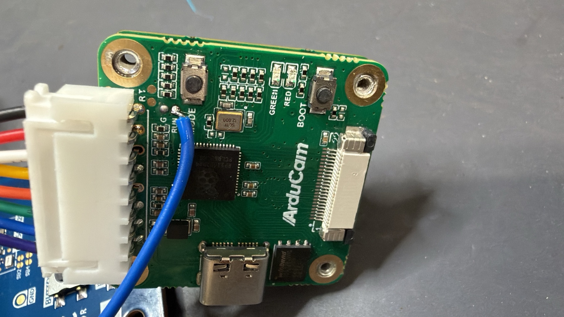
Figure 3. The whole change: one wire, two solder joints.
The exchange behind this sits in Nordic DevZone case 361087, raised in June and answered there.
At YOLO Vision, Shenzhen
On 13 September the unit ran at Ultralytics' YOLO Vision conference in Shenzhen, on Arducam's table at Sony's booth.
It ran firmware v0.6.2, without the reset wire, and it ran through the day with no restarts, per the Arducam engineer who was with it. That is one continuous day of operation rather than a claim about repeated cold starts, and it is worth saying exactly which build it was: the wire and the firmware in this article are what make a cold start reliable, and the unit in Shenzhen had neither. What it had was the printed card that shipped in the box, carrying the power-up order that a unit without the wire depends on.
Visitors asked about the module's price, whether model conversion needs a cloud service or runs locally, and where the SDK lives.
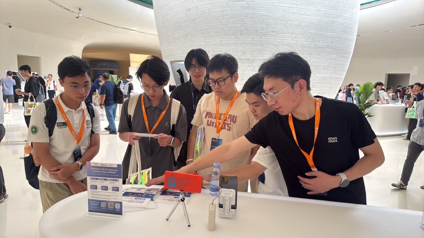
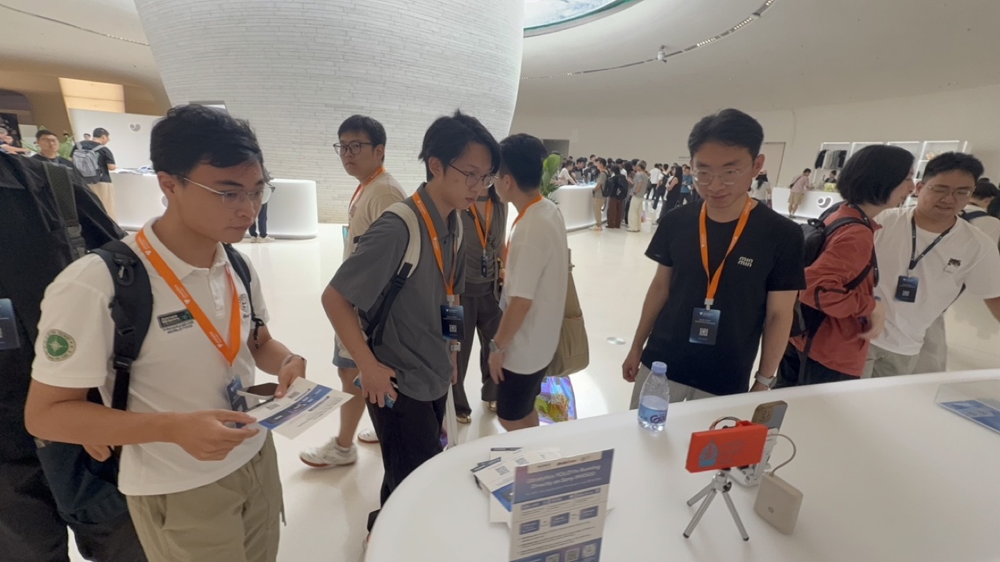
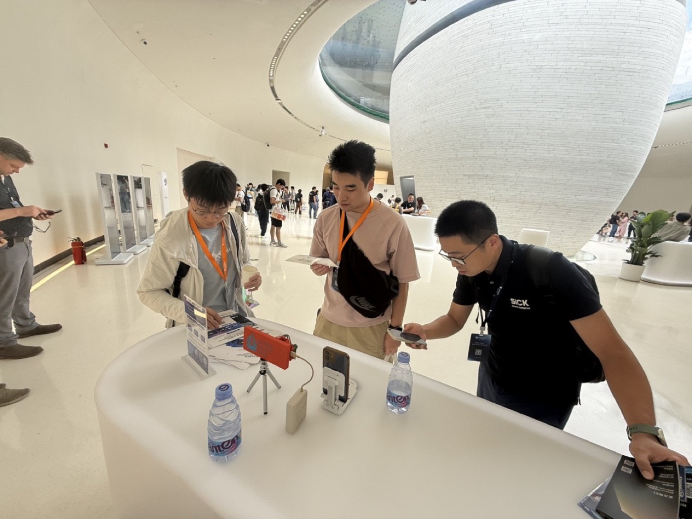
Figure 4. Shenzhen, 13 September. Photographs by Arducam.
What we would ask Nordic for
Three things, in the order they cost us time.
- Ship the Edge AI add-on in the stock nRF Connect SDK manifest, or document the workspace recipe. Today the add-on cannot be used from a Toolchain Manager install at all. The build aborts on four undefined Kconfig symbols, and every evaluator has to discover the custom-manifest workflow for themselves.
- Let the nRF Connect VS Code extension select an existing west workspace. The extension struggles unless the project sits directly inside the workspace, which is what pushed us to our own wrapper script rather than the supported tooling.
- Fix the VDD:IO description in the DK documentation. The user guide and block diagram call it a voltage follower, which reads like a high-impedance buffer. The schematic block is a discrete LDO. That distinction is exactly what decides whether the rail can power a peripheral, and getting it wrong cost us weeks.
Two people are owed thanks by name. Hung Bui answered the DevZone case, worked through the hypothesis with us, asked for the oscilloscope captures that settled it, and suggested powering the camera from an LDO off the 5 V rail, which is what unblocked us at the time. Don Janysek took it through the right channels inside Nordic and made the internal case for us exhibiting at the Portland and Austin events, before any of this had reached a conference floor.
Six principles this firmware runs on
- Size buffers from measurements, not from arithmetic. The JPEG does not scale with the image and the forwarder read does not scale with the frame, so the firmware logs both every run and the budget is set from what it sees.
- Give the hard real-time thread the priority it needs and let everything else be best-effort. A dropped frame costs nothing; a starved audio slab is permanent.
- Put the invariant in the build, not the test plan. A frame too large to borrow would stop the preview while detections carried on, so it is a
BUILD_ASSERTrather than something to notice later. - Let the model package describe itself. Plane order, box format, quantisation and coordinate convention all belong to the package, and the decoder reads them from it.
- Find the reset line early. When a peripheral makes a boot decision once and never re-evaluates it, host-side retry logic cannot reach it. A reset line can.
- Run both conditions in the same sitting on the same bench. It is the difference between a result and an anecdote.
See it live
Ten minutes, one rig, and the whole path from a spoken word to a filtered detection on a phone.
psvision was built at Pretty Smart Labs. The idea and architecture are Antonio Rodriguez's, the firmware and the apps are Emilio Águila Escalante's. The Arducam B0642 is genuinely good and this demo would not exist without it: the hardware note above is about one integration detail, not a verdict on the part.